


CONSTRUCTION
 The next stage is to set up the frames, truly aligned in all planes. Many years ago I made a jig for this purpose, as illustrated in the photo. The basic principle is the ‘headboard’ firmly glued in place, and perpendicular to this, a strip of wood exactly 15mm wide (to match your frame spacing) glued in place. Either side of this are two other strips of wood which are held in place by screws in slots, so that they can move when the screws are loosened.
 The individual frames are placed in the slots between the strips
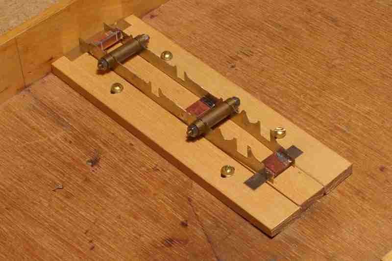 of wood, and gripped in place by squeezing the side strips, and tightening the screws. A couple of strips of metal under the ends of the frames holds them level, and making sure that the frames are tight against the headboard ensures they are aligned. Finally the frames are held upright by temporary spacers which fit into the cut-
It has been suggested to me that my jig would have been better made of aluminium section, but I think this overlooks the fact the aluminium is an excellent heat conductor, perhaps making soldering a lot more difficult.

 Fitting the first of the hornguides requires care so that it is upright, and centrally in its slot so that the bearing slides freely up and down. The photo shows the first one held in place by an aluminium clip, awaiting soldering. Fitting the second hornguide requires equal care, to make sure it is in line with the first, so that the axle is exactly perpendicular to the chassis. The photo shows a length of 1/8th” silver-